Measurement of ABCD parameters of a medium transmission line with magnitude and angle.
Power System
Experiment : Measurement of ABCD parameters of a medium transmission line with magnitude and angle.
Appratus:
- variable Voltage Source (Variac) 230V AC with 2-Pole S/W
- No of π sections: 2 (100Km each)
- value of each component: Resistance = 4 Ohm; Capacitance = 0.47 microF; Inductance: 110mH.
- Voltmeter: 230 V AC (2 Nos)
- Ammeter: 5 A (2 Nos)
- Watt meter: 300V, 5A (1 Nos)
Theory:
Medium Transmission Line
A transmission line having a length of more than 80 kms but less than 250 kms is considered as a medium transmission line. The parameters (Resistance, Inductance, and Capacitance) are distributed uniformly along the line. For a medium transmission line, charging current is appreciable and due to the length of the line the shunt admittance plays a significant role in the calculation of the effective parameters of the line.
The shunt admittance and series impedance are considered as a lumped parameter of the medium transmission line. The medium transmission line is shown below in the diagram.
Many localized capacitance models have been used to make approximate line performance calculations. The following models are commonly used.
- Nominal T model
- Nominal ∏ (pi) model
ABCD parameters of a medium transmission line
In the nominal pi model of a medium transmission line, the series impedance of the line is concentrated at the centre and half of each capacitance is placed at the centre of the line. The nominal Pi model of the line is shown in the diagram below.
In this circuit,
By ohm’s law
 Sending-end current is found by applying KCL at node c
or
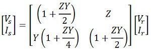
 Equations can be written in matrix form as
Also,
Hence, the ABCD constants for nominal pi-circuit model of a medium line are
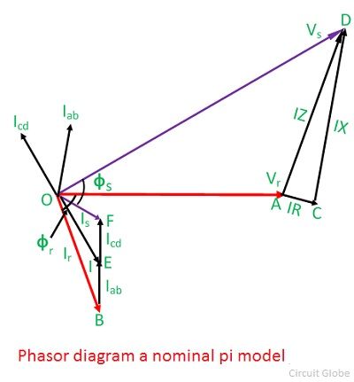
Phasor diagram of nominal pi model
The phasor diagram of a nominal pi-circuit is shown in the figure below.
 It is also drawn for a lagging power factor of the load. In the phasor diagram the quantities shown are as follows;
OA = Vr – receiving end voltage. It is taken as reference phasor.
OB = Ir – load current lagging Vr by an angle ∅r.
BE = Iab – current in receiving-end capacitance. It leads Vr by 90°.
The line current I is the phasor sum of Ir and Iab. It is shown by OE in the diagram.
AC = IR – voltage drop in the resistance of the line. It is parallel to I.
CD = IX -inductive voltage drop in the line. It is perpendicular to I.
AD = IZ – voltage drop in the line impedance.
OD = Vs – sending–end voltage to neutral. It is phasor sum of Vr and IZ.
The current taken by the capacitance at the sending end is Icd. It leads the sending–end voltage Vs by 90
OF = Is – the sending–end current. It is the phasor sum of I and Icd.
∅s – phase angle between Vs and Is at the sending end, and cos∅s will give the sending-end power factor.
ABCD Parameters of a Two Port Network
In any 4 terminal network, (i.e. linear, passive, bilateral network) the input voltage and input current can be expressed in terms of output voltage and output current. Each port has 2 terminals to connect itself to the external circuit. Thus it is essentially a 2 port or a 4 terminal circuit, having:

![]() Given to the input port PQ.
Given to the input port PQ. Given to the output port RS.
Now the ABCD parameters of the transmission line provide the link between the supply and receiving end voltages and currents, considering the circuit elements to be linear in nature.
Thus the relation between the sending and receiving end specifications is given using ABCD parameters by the equations below.
Now in order to determine the ABCD parameters of the transmission line let us impose the required circuit conditions in different cases.
ABCD Parameters When Receiving End is Open Circuited

The receiving end is open-circuited meaning the receiving end current IR = 0.
Applying this condition to equation (1) we get,
Thus it’s implied that on applying open circuit condition to ABCD parameters, we get parameter A as the ratio of sending end voltage to the open circuit receiving end voltage. Since dimension-wise A is a ratio of voltage to voltage, A is a dimensionless parameter.
Applying the same open circuit condition i.e IR = 0 to equation (2)
Thus it’s implied that on applying open circuit condition to ABCD parameters of a transmission line, we get parameter C as the ratio of sending end current to the open circuit receiving end voltage. Since dimension wise C is a ratio of current to voltage, its unit is mho.
Thus C is the open circuit conductance and is given by
C = IS ⁄ VR mho.
ABCD Parameters When Receiving End is Short Circuited

Receiving end is short circuited meaning receiving end voltage VR = 0
Applying this condition to equation (1) we get, Thus it’s implied that on applying short circuit condition to ABCD parameters, we get parameter B as the ratio of sending end voltage to the short circuit receiving end’s current. Since dimension wise B is a ratio of voltage to current, its unit is Ω. Thus B is the short circuit resistance and is given by
B = VS ⁄ IR Ω.
Applying the same short circuit condition i.e VR = 0 to equation (2) we get Thus it’s implied that on applying short circuit condition to ABCD parameters, we get parameter D as the ratio of sending end current to the short circuit receiving end current. Since dimension wise D is a ratio of current to current, it’s a dimensionless parameter.
∴ The ABCD parameters of the transmission line can be tabulated as:
| Parameter | Specification | Unit |
| A = VS / VR | Voltage ratio | Unit less |
| B = VS / IR | Short circuit resistance | Ω |
| C = IS / VR | Open circuit conductance | mho |
| D = IS / IR | Current ratio | Unit less |
Circuit Diagram:
Precaution:
- Use proper rated fuse
- The ground points of the equipment must be grounded firmly.
- Always keep the MCB to OFF state and the Variac to zero before conducting experiment.
- Make sure that the voltage rating does not pros 300V and current rating of 1 Amp.
Procedure:
- Keep MCB in OFF condition & Variac in zero position.
- Connect the circuit as shown in figure.
- Make sure that circuit is connected properly and turn on supply.
- Initially keep receiving and open circuit (connect voltmeter across point A and B shown in the circuit).
- Set required voltage (Vs) and note down the quantities which are required for the practical as per the given observation table.i-e(Is,Vr,W). In this in this open circuit test Ir will be zero Amp.
- reduce the input voltage to zero volt.
- Now conduct short circuit test now connect ammeter across point A and point B.
- Increase the input voltage. (keep input voltage in safe limit also make sure that current form sending inside and receiving and side should be below 1 ampere)
- Note down the reading you will get Vs,Is,Ir,W.
- In short circuit test Vr will be zero volt.
- Note down both open circuit and short circuit readings in given observation table.
- Calculate the equivalent ABCD parameters.
|
Sr. No |
Condition |
Vs |
Is |
Vr |
Ir |
W |
|
1 |
Open Circuit Cndn |
80 |
0.049 |
84.2 |
0 |
0 |
|
2 |
Short Circuit Cndn |
79 |
0.946 |
0 |
1 |
8*5= 40 |
*Above readings are for Example
purpose
Calculations:
D = Is/Ir (Vr=0 i.e SC Test) = 0.946/1 = 0.946
Theoretically:
As we have,
Resistance = 4 Ohm; Capacitance = 0.47 microF; Inductance: 110mH....... per 100Km
Total length of 220 KV line is 200 Km.
so,
Impedance
z=R+jωL
z= 4+j2π 50(110*10^-3)..........for 100km
Ztotal=Z200=
Z= [4+j2π 50(110*10^-3)]*2
Z=8+j69.12
Z=69.58 ∠83.39o
Admittance
y=g+jωC...............(conductance g is negligible)
Y= [j1.48*10^-4]*2
Y= 2.95*10^-4∠90o
Now, we can derive the ABCD parameters of a medium transmission line as:A=D = (
1 + YZ/2 )
={1+[(2.95*10^-4∠90o)(69.58 ∠83.39o)]/2}
= 0.99∠0.0680
B=Z
=69.58 ∠83.39o
C = Y ( 1 + YZ/4 )
=(2.95*10^-4∠90o){1+[(2.95*10^-4∠90o )(69.58 ∠83.39o )]/4}
= 2.93*10^-4∠90.03o
Results:
|
Sr. no. |
Parameter |
practically |
Theoretically |
|
1 |
A |
0.95 |
0.99∠0.0680 |
|
2 |
B |
79 |
69.58 ∠83.39o |
|
3 |
C |
5.82*10^-4 |
2.93*10^-4∠90.03o |
|
4 |
D |
0.946 |
0.99∠0.0680 |
Conclusion: Thus, we have calculated ABCD parameters of Medium length T/Lwith magnitude and angle having length of 200 Km.


Comments
Post a Comment
thanks for comment