Performance study of the effect of VAR compensation using capacitor bank on the transmission line.
Experiment: Performance study of the effect of VAR compensation using capacitor bank on the transmission line.
Apparatus:
- variable Voltage Source (Variac) 230V AC with 2-Pole S/W
- Transmission line model of π sections: (100Km each)
- value of each component: Resistance = 4 Ohm; Capacitance = 0.47 microF; Inductance: 110mH.
- Voltmeter: 230 V AC (2 Nos)
- Ammeter: 5 A (2 Nos)
Theory:
Power system supply or consumes both active and reactive power. While it is the Active power that contributes to the energy consumed or transmitted, reactive power does not contribute to the energy. Reactive power is either generated or consumed in almost every component of the system. Reactive power compensation is defined as the management of reactive power to improve the performance of AC systems.
Why reactive power compensation is required?
1. To maintain the voltage profile
2. To reduce the equipment loading
3. To reduce the losses
4. To economics
5. To Improve Power Factor
6. To Improve Regulation.
There are two aspects to reactive power compensation
1) Load compensation
The main objective of the load compensation is to increase the power factor of the system, to balance the real power drawn from the system, to compensate
voltage regulations.
2) Voltage support
The main purpose is to decrease the voltage fluctuation at a given terminal of transmission line. Therefore the reactive power compensation improves the
stability of AC system.
What is Reactive power?
Methods of Reactive power compensation:
- Synchronous condensers
- Static VAR Compensators
- Static synchronous compensators(STATCOM)
- Series compensation
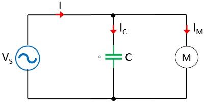
Suppose we have a circuit shown here,
 Reducing power losses: Compensating the load’s lagging power factor with the bus connected shunt capacitor bank improves the power factor and reduces
current flow through the transmission lines, transformers, generators, etc. This will reduce power losses in the equipment, cables and transmission lines.
Increased utilization of equipment: Shunt compensations with capacitor banks reduces kVA loading of lines, Transformers, and Generators, which
means with compensation they can be used for delivering more power without overloading the equipment. Shunt compensation can be installed near the load, in a distribution substations and along the distribution feeder.
- It improves the power factor of the source current
- It reduces capital investment per megawatt of the load
To provide reactive VAR control in order to support the power supply system voltage and to filter the harmonic currents in accordance with Electricity Authority recommendations, which prescribe the permissible voltage fluctuations and harmonic distortions, reactive power Q (VAR) compensators are required.
Reactive power is the portion of electricity that establishes and sustains the electric and magnetic fields of alternating current equipment. Reactive power must supplied to most types of magnetic equipment, such as motors, Transformers, etc.
Having said the types of compensation, in this article we are going to discuss mainly about Shunt compensation using Capacitor bank.
Since most loads are inductive in nature they consume lagging reactive power, so the compensation required is usually shunt capacitor bank.
shunt Capacitor Banks: In this method, a bank of capacitors forms a connection across the load. As we know that the capacitor takes the leading reactive power, thus this causes the decrease in power taken from the source. This resultantly improves the value of the power factor of the system. This is further classified as series and shunt compensation.
As we have discussed at the beginning itself that the value of the power factor must be unity, thus, to achieve this, here the capacitor across the terminals of the motor must be changed according to the load variation of the induction motor. This is known as dynamic power factor control as reactive power compensation is done by switching in or out of the capacitors at all load conditions.
So, In order to have a continuous controlling of pf of the system, various small rating capacitors must be required. The switching in and out of the capacitor was done by mechanical switches earlier but now thyristors are used which helps in regulating the flow of reactive power and controlling reactive power voltage by rapid switching of the static capacitors.
Shunt capacitors are employed at substation level for the following reasons:
Use of capacitive (shunt compensation) on various part of the power system improves power factor, Reduce power losses, improves voltage regulation and increased utilization of equipment.
Circuit Diagram:
- make the connection as shown in figure.
- Switch on the supply.
- Maintain sending in voltage constant adjusting auto transformer.
- take corresponding receiving in voltage and sending it current reading without connecting capacitor.
- Now, connect a capacitor in circuit at receiving end and take readings for voltage current.
- Turn off main switch and remove the connections.
- Calculate necessary parameters.
|
Condition |
Vs |
Is |
Ir |
Vr |
W |
|
Without Capacitor |
144 |
0.475 |
0.5 |
112.5 |
64 |
|
With Capacitor |
144 |
0.54 |
0.5 |
125 |
80 |
Conclusion:In this practical we have studied the effect of capacitor when connected across the receiving end. Hey above result also shows that in the total power part of active power is increased. voltage regulation of transmission line has been improved which is the part of var compensation.
Write Answers of following Questions:
- Define Compensation
- Give and Explain Different type of compensation.
- what are advantages of Shunt Compensation.
- what are advantages of Series Compensation.
- What is STATCOM
- What is FACTS


Comments
Post a Comment
thanks for comment