Types of a Lightning Arrester
- Get link
- X
- Other Apps
choice of lightning arrester depends upon the following factors:
- Voltage
- Current
- Reliability
- Space available for installation
Types of lightning arresters.
- Rod Gap Arrester
- Sphere Gap Arrester
- Horn Gap Arrester
- Multiple-Gap Arrester
- Impulse Protective Gap Arrester
- Electrolytic Arrester
- Expulsion Type Lightning Arrester
- Valve Type Lightning Arresters
- Thyrite Lightning Arrester
- Auto valve Arrester
- Oxide Film Arrester
- Metal Oxide Lightning Arrester
Rod Gap Arrester
 |
It is one of the simplest types of Lightning Arresters. In the before-mentioned type, there is a gap between the end of the two rods. These two rods get connected to the earth and the line directly. The gap gets filled with air.
When there is a higher voltage on the line, the air ionizes, producing a spark. In this fashion, the fault current passes to the earth. The process is explicated above in the snippet. Hence, the equipment is saved from potential damage.
Sphere Gap Arrester

In such types of lightning arresters, an air gap is provided between two spheres. Here, one of the spheres is grounded, and another is connected to the line. The diagram below represents the process in detail.
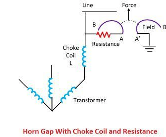
There is a choking coil between the transformer and the ground, which heats up when the voltage rises. The air between the spheres heats up and tries to escape. But the corona discharge mechanism ionizes the air and the fault current passes through it. Thus, it saves potential damage to the device.
Horn Gap Arrester

This contains two horn-shaded pieces of metal. These two are separated by a small air gap and connected in a shunt between each conductor and earth. The distance between the two electrodes is optimum. This distance is filled with air that ionizes on fault current passage.
Hence, the fault current is passed to the earth, and the inherent damage is stopped.
Multiple Gap Arrester

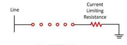
The schematic diagram above shows the details in brief. It consists of a small series of insulated through an air gap. The number of gaps depends upon the voltage. The gaps protect the device through the corona discharge. In it, air ionizes, and fault current passes through the ground. A resistor is added to stop the fault current even further.
Electrolytic Arrester
It has a high discharge capacity. It operates on the basic principles of an electrolytic cell. Expressly, here aluminum hydroxide deposits on the aluminum plates. The plate acts as a high resistor to a low voltage value and vice versa for a critical value.
A voltage of more than 400 volts punctures the impedance. Hence the fault current passes to the ground.
Thyrite Lightning Arrester
These types of lightning arresters are commonly used for extremely high voltage conditions. It consists of a ceramic material called Thyrite, which has a variable resistance. The resistance is inversely proportional to the voltage applied at the ends of it.
It contains a disc that is made conductive on both sides by spraying some conducting material. The disc is contained inside a translucent porcelain container. It is used as a joint in the container.
When the lightning takes place, the voltage gap is filled through the breakdown of gaps. This saves the device from implied damage.
Metal Oxide Lightning Arrester

It is also called Zinc Oxide diverter. The schematic diagram below shows the process.
These types of diverters are known as gapless surge diverters. The base material here is zinc, and the oxide manufactured is zinc oxide. It is a semiconducting material. This material is anesthetized by adding fine powders of insulating oxides.
This powder is treated and then stuffed into a disc-shaped structure. The disc is then enclosed in an earthenware housing filled with sulfur hexafluoride.
Thus, the arrester consists of a potential obstacle at the edges of zinc oxide. This potential barrier constrains the river and pathways of the current. Under normal conditions, it stops the flow of current. But when there is a potential breakage, the barrier collapses and the fault current passes to the ground.
Thus, this stops the surge from damaging any device.
- Get link
- X
- Other Apps

